I've bought a somewhat cheap car MP3 player a few years ago on the reason that it had Bluetooth support and nice amber lights to complement the design of my E39.
I understand some people will come here looking for a wiring diagram so I should start with that first:
Model: Watson CRC8060MU


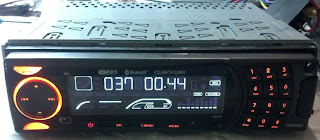
Some of the features:

 To have a baseline I measure the consumption with no speaker load. Anyway my car has a built-in 10-channel amplifier so the consumption should be similar: around 10 Watts.
The setup is on the right, I use a small 1Ah battery as a current buffer since my supply shuts down at 2A. I found out later that this was not necessary.
The highest consumption was with an MP3 CD, measuring at 1.7A while buffering the tracks.

 Using another cheap piece of equipment (the meter on the right) I measure the USB voltage at 4.94V, a bit on the low side. Any healthy 5V regulator usually puts out more than 5V without a load.


The unit seems built with serviceability in mind, using normal screws, connectors and labeled pins.
Most of the inside of the unit is taken up by the CD tray.
The "security" system consists of a detachable front panel.

... which is connected to the main body via a 20-pin connector ....

... and the ground contact.

The front panel houses the display, buttons, USB port, AUX input, handsfree microphone and IR receiver.


Underneath the display there is a CT6523 LCD driver. I have a feeling the backlighting LEDs are also driven by this chip since the lights dim in unison. Unfortunately I just realized this now so I cannot really check on it but it would be a pretty smart and cost-effective solution.

Soldering quality is surprisingly good for a unit from Far-East, though there are a few manual solder jobs with the accompanying flux residue.
Tracing back the 20-pin connector to the main body side we can see that the anti-theft measure is probably something that is performed with resistors or connection swapping. I have a wild feeling that at least 2 out of 10 front panels can be interchanged with no issues since I cannot see any trace of an EEPROM or smart chip.

The signals going between the panel and body are:
Why have the volume and mute inputs separate from the other inputs? If my guess is right then it is about system responsiveness: you really don't want any lag when performing volume-related actions on an automotive entertainment system.
Bottom left connector goes to front panel, bottom right connector is the SD card reader and the top-right row of pins goes to the backside ISO connector.

There is a second front panel, hiding the CD tray. It has a CD LED, antitheft LED, small reset button and eject button.

It also houses the Bluetooth chip, Samsung BTTM47C2SA. I cannot find any datasheet on it.


The other chips are just for support:
 The ISO connector (right) is soldered to a riser board, next to the choke, big protection diode and small input capacitor.

Notice the manual solder job with an underpowered iron and the exfoliated power resistors.

 A quick check of the unloaded USB output shows a 1.4V peak to peak variation which means the regulator is oscillating or dying.

A load test (400mA on USB) showed that the regulator input was falling from 10V to 6V causing the output to drop to less than 4V.
Meanwhile, the resistors got pretty toasty as well hinting to a flawed design. I started tracing everything around the regulator and came up with this schematic:

The designers wanted to reduce the power dissipated by the 7805 by distributing some of it to the 3 Watt resistors located in vicinity. The 5V rail also goes to a 1.8V and a 3.3V regulator on the board supplying power to the microcontroller and memory chips. Obviously, when the 5V rail dies it drags everything down with it causing a reset.
The no-load current is at 0.2A since the 1.8V and 3.3V lines use LDOs and not switched-mode (efficient) power supplies.
Let's see how power dissipation would look: we have 11-15V going in and 5V going out. That means a 6-10V voltage drop. With a 0.2A load that's 2W. Adding another 500mA for the USB results in a dissipation of 7W which is quite a lot for a 7805 without a heatsink.
Going with the designer's solution, at 15V the R5+R6 are limiting the current to 1.5A. That means R5 is burning away 6.75W and R6 7.5W, way above their maximum ratings of 3W.
Changing the 7805 with another one cured the issues but still there was a design problem that was causing the linear regulator to fail and the resistors to smoke.
See the mod here: http://hackcorrelation.blogspot.com/2013/09/teardown-and-modding-car-mp3-player_16.html
I understand some people will come here looking for a wiring diagram so I should start with that first:
Model: Watson CRC8060MU


I've always had the issue of not being able to charge anything from the USB port or the unit resetting with some strange USB sticks. Also, the unit lost its settings when cranking the engine with a low battery while it was playing music.
After the jump I start taking it apart to see how it works and what can be done to address the issues.
Some of the features:
- MP3/WMA/WMV/WAV/... playback from CD, USB (FAT and NTFS) , SD Card
- AM/FM with Traffic Announcements, RDS and automatic date adjustment from RDS
- Bluetooth handsfree with built-in mic and A2DP streaming
- Recording from FM/CD to USB in either MP3 or WMA format
- AUX-IN playback
- 4x50W (yeah, right!) and supplementary RCA outputs
- 4 equalizer presets plus a custom one and "loudness" option
- Settable high-pass/low-pass filter frequency for subwoofer
- Backlight dimming support (more on that later)
- Remote control
A pretty decent feature set for a price not higher than 100 USD. What's even more surprising is a working implementation of A2DP before the standard was even completed and the testing choices were pretty limited, only a handful of phone providing Bluetooth 2.0 at that time. So far it stood the test of all smartphones and performed better than most of the OEM units.
The backlight for the buttons is a nice amber color matching the backlighting of my car. There's a pin for dimming but it seems to function in reverse. That is, if I turn the lights on the display dims (as expected) but if I dim the interior lights the display brightens up. I will probably make a follow-up post on a future modification, it should involve nothing more than a transistor and a couple of resistors.
I won't go on with the feature set but suffice to say the brain of the unit consists of a Telechips TCC8601 - which is now found in a lot of OEM units (Seat, Citroen, Peugeot, Renault, ...)

 To have a baseline I measure the consumption with no speaker load. Anyway my car has a built-in 10-channel amplifier so the consumption should be similar: around 10 Watts.
The setup is on the right, I use a small 1Ah battery as a current buffer since my supply shuts down at 2A. I found out later that this was not necessary.
The highest consumption was with an MP3 CD, measuring at 1.7A while buffering the tracks.

 Using another cheap piece of equipment (the meter on the right) I measure the USB voltage at 4.94V, a bit on the low side. Any healthy 5V regulator usually puts out more than 5V without a load.

The unit seems built with serviceability in mind, using normal screws, connectors and labeled pins.
Most of the inside of the unit is taken up by the CD tray.
Front panel

... which is connected to the main body via a 20-pin connector ....

... and the ground contact.

The front panel houses the display, buttons, USB port, AUX input, handsfree microphone and IR receiver.


Underneath the display there is a CT6523 LCD driver. I have a feeling the backlighting LEDs are also driven by this chip since the lights dim in unison. Unfortunately I just realized this now so I cannot really check on it but it would be a pretty smart and cost-effective solution.

Soldering quality is surprisingly good for a unit from Far-East, though there are a few manual solder jobs with the accompanying flux residue.
Tracing back the 20-pin connector to the main body side we can see that the anti-theft measure is probably something that is performed with resistors or connection swapping. I have a wild feeling that at least 2 out of 10 front panels can be interchanged with no issues since I cannot see any trace of an EEPROM or smart chip.

The signals going between the panel and body are:
- encoder up and down (probably volume, not sure how next/prev is signalled)
- LV (low-voltage) SPI pins, probably used for the LCD driver (SCK, SI, CE)
- INH - mute?
- USB data
- USB 5V, separate pin from the panel's 5V supply
- reset pin
- backlight input
- microphone and stereo aux inputs, having a separate analog ground (AGND)
- ADKIN0-2 I suspect are the pins multiplexing the button inputs
- REM0 probably the infrared receiver output
Why have the volume and mute inputs separate from the other inputs? If my guess is right then it is about system responsiveness: you really don't want any lag when performing volume-related actions on an automotive entertainment system.
Main body
The backside is nicely traced and labeled and it consists mostly of vertical traces while the top side has mostly horizontal traces. The solder plane on the top left is the "heatsink" for the 5V regulator.Bottom left connector goes to front panel, bottom right connector is the SD card reader and the top-right row of pins goes to the backside ISO connector.

There is a second front panel, hiding the CD tray. It has a CD LED, antitheft LED, small reset button and eject button.

It also houses the Bluetooth chip, Samsung BTTM47C2SA. I cannot find any datasheet on it.

A quick overview of the various interconnecting pieces

The main processor is the Telechips TCC8601 all-in-one solution providing all but the kitchen sink.
The real-time stuff is performed by a Samsung 3F9454BZZSK94 sitting in the lower right corner. Funny enough, this SAM88RCRI S3F microprocessor has a beta symbol painted on it. From my observations it deals with performing the correct cycling of the power to various peripherals. It cannot really do heavy stuff since it only has at most 4 kbytes of ROM and 208 bytes of RAM.

The other chips are just for support:
- Microchip/SST SST39VF1601 - 1 MByte flash
- Hynix HY57V641620FTP - 143Mhz SDRAM, 4 Mbytes?
- Princeton Technology PT2579-S - RDS demodulator
- Texas Instruments TLV320 AIC32B - stereo audio codec
- 7313 (?) - possibly a TDA7313 stereo audio processor
- AT9257 - unknown, has to do with radio stuff, possibly PLL
 The ISO connector (right) is soldered to a riser board, next to the choke, big protection diode and small input capacitor.
The current path to the audio amplifier (left) is thus pretty short. I'm not even sure there are a lot of ways to do this given the automotive constraints.
Actually, the point of interest is the area on the lower right, which I'll discuss next
Power circuit
I've traced the USB power output through the front panel, the other front panel, board connectors and traces and back to this LM7805 regulator sitting quietly bent back on its pins.

Notice the manual solder job with an underpowered iron and the exfoliated power resistors.

 A quick check of the unloaded USB output shows a 1.4V peak to peak variation which means the regulator is oscillating or dying.
A load test (400mA on USB) showed that the regulator input was falling from 10V to 6V causing the output to drop to less than 4V.
Meanwhile, the resistors got pretty toasty as well hinting to a flawed design. I started tracing everything around the regulator and came up with this schematic:
The designers wanted to reduce the power dissipated by the 7805 by distributing some of it to the 3 Watt resistors located in vicinity. The 5V rail also goes to a 1.8V and a 3.3V regulator on the board supplying power to the microcontroller and memory chips. Obviously, when the 5V rail dies it drags everything down with it causing a reset.
The no-load current is at 0.2A since the 1.8V and 3.3V lines use LDOs and not switched-mode (efficient) power supplies.
Let's see how power dissipation would look: we have 11-15V going in and 5V going out. That means a 6-10V voltage drop. With a 0.2A load that's 2W. Adding another 500mA for the USB results in a dissipation of 7W which is quite a lot for a 7805 without a heatsink.
Going with the designer's solution, at 15V the R5+R6 are limiting the current to 1.5A. That means R5 is burning away 6.75W and R6 7.5W, way above their maximum ratings of 3W.
Changing the 7805 with another one cured the issues but still there was a design problem that was causing the linear regulator to fail and the resistors to smoke.
See the mod here: http://hackcorrelation.blogspot.com/2013/09/teardown-and-modding-car-mp3-player_16.html
Comments
Post a Comment
Due to spammers, comments sometimes will go into a moderation queue. Apologies to real users.