Update: if you came here looking for a fix to the annoying beep I might have one - if you are feeling handy: take the unit apart, desolder one wire from the battery terminal, discharge the capacitor (by touching the disconnected wire to the other wire) and solder it back on.
Take care not to short the battery, you only want to discharge the circuit with the battery disconnected.
If you do not understand perfectly what you need to do then please do not attempt this!
This has 'fixed' one of my units (since 6 months) and has quitened another one for ~2 months.
Back to the original post:
On of the my smoke detectors - installed by the landlord under legal obligation - started acting up by emitting annoying short beeps and random intervals, moreso during the night.
The producer boasts a 10-year service lifetime, smoke detection as well as heat detection.
Since they are the "non-user-serviceable" type nothing else remains than to take it apart and see what makes it tick. Spoiler: it's less complicated than you might think.

The housing comes apart by first prying the small plastic retainers on the underside edge. Apart from the VERY LOUD piezo, a CR123 battery and a "snooze" button there's not much too see. But all the interesting stuff is beneath the button so we need to take that plastic frame off.
Peeling off the sticker reveals some other 3 retaining clips which means the mainboard sitting under the button can be simply unscrewed off. You do not need to peel the sticker, it's enough to just screw the button assembly counter-clockwise.

Oh, the big plastic lever above is pressed in when the sensor is affixed to the ceiling mount. This in turn presses up the metal tongue below, breaking off a contact on the board and waking up the sensor.
The board has very little to it, the centerpiece being PIC16F785 (low-voltage variant), so let's see what it can do:
- 32kHz-8Mhz internal oscillator
- 1-8uA current consumption (chip only)
- high-speed comparator module with programmable reference
- integrated 3MHz GBWP OpAmp
- 10-bit ADC
- 10-bit PWM
...plus the usual Microchip stuff. It seems like a hybrid uC, like 16F728 + LM331/393 + LM324/358, something good to have in the parts drawer :)
Before seeing the datasheet I was trying to see where the opamp would be but it seems like it's integrated in the chip.

Power is provided by a non-rechargeable CR123 cell, which typically provides 1500mAh @ 3V. The PIC will run as low as 2V, possibly even lower. My cell was still measuring 3V so I don't know why the chip was signalling low battery after one year of stand-by.
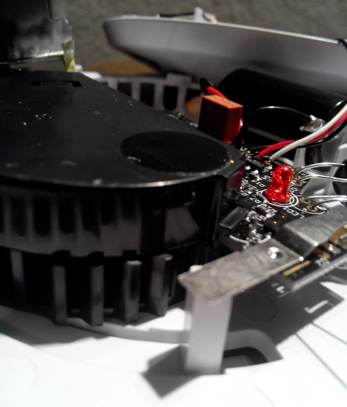
There's a big orange fuse in the middle, marked 315mA @ 250V, a blue capacitor at 220uF, a black 3-pin component marked with D4 on the board which I have not idea what it is. One pin is marked P (primary?), the other one S (secondary?) so it must be a transformer since the piezo needs >50V in order to be loud.
A tactile chip, signaling LED, some SMD passives and a random diode complete the picture.

The gold pads look very much like some automated testing and programming interface. There is a diode to the left beneath a metal shield and another similar-looking one to the right.
These probably make up the heat sensors and I can assume it works on of the two ways:
- Measuring the -2mV/C slope and having it calibrated at factory
- Feeding both diodes into an integrating comparator and see if the non-shielded one heats faster

Underneath the black housing there are two infrared diodes - one is probably used as an LED and the other one as a receiver. Or it might be that one of them is actually an IR photodiode. It's cheaper to use just LEDs though and it works mostly the same. Since the producer is pumping out millions of these per year they might go through all cost-cutting measures they could.

Another look at the bare board:

And one at the detector pattern:

The slit arrangement is probably blocking stray IR light from entering the enclosure but smoke may pass through.
Theory 1:
One LED emits a burst of light and if there is no smoke inside the slits will just redirect/absorb the beam. If there is some smoke inside it will reflect light on the IR sensor causing the uC to trip the alarm.
Theory 2:
The LED and receiver have almost unconstrained line-of-sight but they are positioned slightly off-center. If smoke enters the enclosure it will absorb some of the light which causes the detector to drop its output.
I expect the sensor wakes up periodically (each 40 seconds or so), does an internal check (battery voltage, sensor output range) and then compares the values from the sensors with the last saved ones. It then saves the new analog values for the sensors and goes back to sleep. If the battery is low it will cheerfully beep before sleeping.
The fire condition is triggered either by interrupting the uC from sleeping or once every 40s. I have not tested this, but detecting a fire within 40s still seems ok. Maybe the uC sleeps less when the conditions are getting worse in order to react faster.
The sound is generated by doing PWM in the uC which is then voltage-multiplied by the black transformer and fed into the piezo.
The sound is generated by doing PWM in the uC which is then voltage-multiplied by the black transformer and fed into the piezo.
That's about all there is to this fire detector. I expected radioactive materials and chemical sensors but it's much simpler than that. A pair of small-signal diodes are used as temperature [gradient] detectors and a pair of IR diodes do smoke detection.
I expect the cost of mass-producing these in the millions to be below the 5 USD mark but they sell for around 25 EUR ~ 35 USD.
This setup seems to work rather reliably and likes to disapprove loudly of my cooking.
Takk for den fantastiske innlegg! Denne informasjonen er veldig bra og takket være massevis for å dele det :)
ReplyDeleteLiten røykvarlser
This comment has been removed by a blog administrator.
ReplyDeletefantastic work! thanks!
ReplyDeleteNice blog provides many informative and helpful articles. Thanks for sharing the information. Looking for more updates in future.
ReplyDeleteSmoke Detector Alarm
Hello. Out of curiosity, I made a full schematic for this thing, fortunately, double-sided only PCB made this quite easy task although somewhat time-consuming. You did a really good job with assumptions without the exact scheme. To clarify some points, when I saw random diagnostic data for these units at www.mikrocontroller.net/attachment/367846/Auslesse_FireAngel_ST-620.JPG I concluded that "reflection threshold" and "smoke threshold" indicate there is enough sensitivity room space for the whole detection system to work in both modes with smoke or without just for testing purposes. So when there is no obvious condition where smoke can easily scattering the beam light, the almost black surface of the fixture, in reality, isn't perfectly none reflective, and double stage amplifier with x100 gain plus some custom photodiode (metal shield protects that sensitive area against external electromagnetic coupling) and quite a beefy IR light beam pulse at about half an ampere of the current (which is obtained only via 220uf tank and very efficient (low Vsat-c-e) PNP switch transistor, because the average current is only about 3mA limited by R7 1K resistor) is indeed enough to catch weak black only reflected beams. Going forward, looking directly at the scheme there is no possibility to wake up from an external event in another way than a physical microswitch, so in case of heat or smoke the only way to detect these is periodic measurement. At least from that what I can tell optical barrier alone is scanned (short single pulse, just only long enough to discharge the 220uf tank) with 10 seconds intervals. I have no idea (no scope or analyzers was used) how often are sampled two 1n4148 diodes are connected in series as I believe for lower power consumption and better dynamic range (-4mV/°C instead half of that) or battery voltage btw, at that same circuit area. Finally the buzz. At first, I thought the same that piezoelectric cone is PWM'ed from PIC but it is not, it is just a standalone, dead simple - only one active transistor generator (although quite beefy 85db@3meters loud) utilizing feedback equipped version of the piezoelectric transducer which is enabled by low level from micro at the common trace connection of R11 & R20. D4 wrongly mentioned in the article belongs to the 15V Zener diode which clamps the output of the n-ch Mosfet (RTL035N03FRA) against spikes flowing from the center tap of the T1 high voltage (step-up) transformer. I think it is worth mentioning that there is also some kind of anti-tamper circuit or expire "safety executor" - maybe? What I mean, there is a resistive network controlled by one of the GPIOs from PIC. When driven it will be simply constantly drawn about 0.07-0.08C of current draining battery to nearly zero (well almost, just not below typical PN junction threshold which is anyway low enough in this case) in a short period. From the address link posted above, it's clear that this thing starts to counting time (hours) right after the manufacture (some sort of initialization as the power source is always permanently present and on) and at least a self-killing mechanism would make sense here although I would assume that in parallel there could be also implemented some anti-tamper protection for example based on IR leakage already mentioned in your article.
ReplyDeleteCool description. If you want to share the schematic, feel free to leave a link or send it to me, and I can attach it here, with credits.
Delete