Being on the hunt for the cheapest wireless temperature and humidity sensors led me to FreeTec NC-7345-675 - sold by pearl.de at the fair price of 10E, though I might have paid even less for them.
The requirements were: multi-channel, have at least 0.5C accuracy and provide humidity readout. Rolling your own can easily cost more than that.
The sensors pair with this weather station.
The goal is to store all the data on an SBC and provide a nice HTML frontend with long-term statistics and heating automation.
EDIT: blogger removed without warning all the newlines from my code, I had to redo some of those
With the main board detached from the zebra display connector, we can see the coil antenna at the top and the wires for the humidity sensor running at the bottom right.
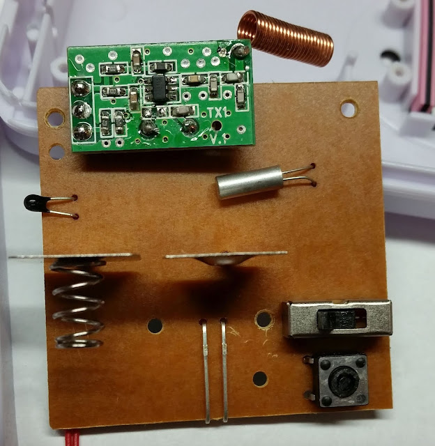
Judging by the traces going from the SW-CH part directly into the chip it seems there is no way to force additional channels.

On the other side, the top part is the 433Mhz transmitter. Behind this small board there's also a crystal oscillator. Beneath it, to the left, is the temperature sensor, and, to the right, the watch crystal.
The sliding switch at the bottom right allows selecting between the three possible channels.
I have no idea what the part at the bottom right does - it looks like a switch but it's actually a trimmer resistor with the top cut off. It might adjust how often the sensor sends data or the power.
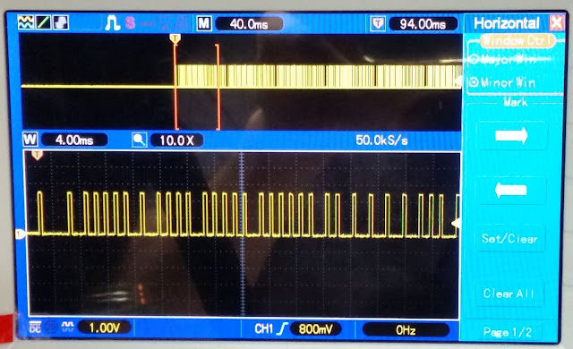
It seems that with each update the sensor sends 9 packets with a length of 36 bits each.
In the screenshot below I've marked the 0s and 1s to aid in decoding.
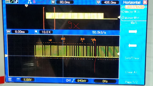
Measuring the signal yields that the encoding scheme is: 480us time unit = T. Each 0 bit is represented by T+2T. Each bit 1 is T+4T. The spacing between packets is ~8T (3900us):
The library had to be updated to support peekInt:

The requirements were: multi-channel, have at least 0.5C accuracy and provide humidity readout. Rolling your own can easily cost more than that.
The sensors pair with this weather station.
The goal is to store all the data on an SBC and provide a nice HTML frontend with long-term statistics and heating automation.
EDIT: blogger removed without warning all the newlines from my code, I had to redo some of those
Hardware
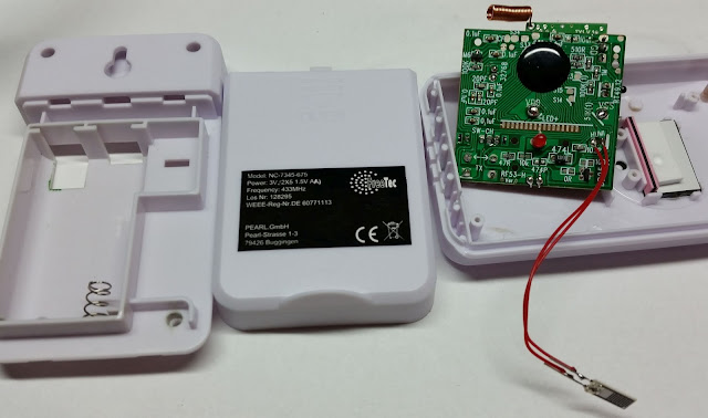
The first step is to open up the sensors and see what we are dealing with.
With the main board detached from the zebra display connector, we can see the coil antenna at the top and the wires for the humidity sensor running at the bottom right.
Judging by the traces going from the SW-CH part directly into the chip it seems there is no way to force additional channels.

On the other side, the top part is the 433Mhz transmitter. Behind this small board there's also a crystal oscillator. Beneath it, to the left, is the temperature sensor, and, to the right, the watch crystal.
The sliding switch at the bottom right allows selecting between the three possible channels.
I have no idea what the part at the bottom right does - it looks like a switch but it's actually a trimmer resistor with the top cut off. It might adjust how often the sensor sends data or the power.

Encoding scheme
I've connected the DATA pin from the TX1 board directly to the oscilloscope so I can get clean readings, without any radio receiver noise.It seems that with each update the sensor sends 9 packets with a length of 36 bits each.
In the screenshot below I've marked the 0s and 1s to aid in decoding.

Measuring the signal yields that the encoding scheme is: 480us time unit = T. Each 0 bit is represented by T+2T. Each bit 1 is T+4T. The spacing between packets is ~8T (3900us):

Software tools
Next, I took the rc-switch library for Arduino and made some heavy modifications to it: instead of keeping all the timings in an array I moved them into a circular buffer.The library had to be updated to support peekInt:
int ByteBuffer::peekInt(unsigned int index){
int ret;
byte *pointer = (byte *)&ret;
pointer[1] = peek(index);
pointer[0] = peek(index+1);
return ret;
}
This allowed me to continuously capture packets while the decoder was still running, and process them in any order without having to worry about array indexes.
Then a new decoding protocol was implemented with the main purpose of writing out timings on the serial console:

The first line is the serial output, the second one is where I marked the potential bits and the third line is the data.
This can be done even with the current rc-switch library, just add the following code after all the receiveProtocolX functions have returned false:
for (int i = 0; i<changeCount ; i++) {
Serial.print(timings[i]);
Serial.print(" ");
}
Serial.println();
However this is running inside the interrupt 'thread' so it cannot be left there. It's time to write a custom decoder that will discard a few of the first few bits and decode the 0s and 1s.
bool RCSwitch::receiveProtocol5(unsigned int changeCount){
unsigned long code = 0;
unsigned long delay = 480;
unsigned long delayTolerance = delay * RCSwitch::nReceiveTolerance * 0.01;
unsigned int size = buffer.getSize();
if (buffer.getSize()<(26*2)){ // clearing the buffer will be taken care of
return false;
}
Serial.print("entering with changecount:");
Serial.println(changeCount); // remove some bits
Serial.print(buffer.getInt());
Serial.print(" ");
Serial.print(buffer.getInt());
Serial.print(" ");
Serial.print(buffer.getInt());
Serial.print(" ");
Serial.print(buffer.getInt());
Serial.print(" ");
Serial.print(buffer.getInt());
Serial.print(" ");
Serial.print(buffer.getInt());
Serial.println(" ");
unsigned int firstSignal;
unsigned int secondSignal;
while(buffer.getSize()>4){
firstSignal = buffer.getInt();
secondSignal = buffer.getInt();
if (THRESHOLD(firstSignal, delay, delayTolerance) && THRESHOLD(secondSignal, delay*2, delayTolerance)) {
code = code << 1;
Serial.print("0");
} else if (THRESHOLD(firstSignal, delay, delayTolerance) && THRESHOLD(secondSignal, delay*4, delayTolerance)) {
code+=1;
code = code << 1;
Serial.print("1");
} else { // Failed
buffer.clear();
code = 1;
Serial.println("resetting");
Serial.println(firstSignal);
Serial.println(secondSignal);
}
}
Serial.println();
code = code >> 1;
if (changeCount > 52) { // ignore < X bit values => noise
RCSwitch::nReceivedValue = code;
RCSwitch::nReceivedBitlength = (changeCount - changeCount % 2) / 2 - 12;
RCSwitch::nReceivedDelay = delay;
RCSwitch::nReceivedProtocol = 5;
}
if (code == 0){
RCSwitch::nReceivedValue = NULL;
return false;
}else if (code != 0){
return true;
}
}
The output from a code similar to the one above, amended manually with the values that were being displayed by the sensor and the chosen channel:
29.6 38% ch3
Received 1960 / 480bit Protocol: 480
entering with changecount:73
484 972 01110001010000100101000111100100110
Received 168988454 / 24bit Protocol: 5
entering with changecount:69
1016 1288 110001010000100101000111100100110
Received 168988454 / 22bit Protocol: 5
entering with changecount:69
936 1368 110001010000100101000111100100110
Received 168988454 / 22bit Protocol: 5
entering with changecount:69
880 1420 110001010000100101000111100100110
Received 168988454 / 22bit Protocol: 5
*********************************************
29.6 37% ch3
Received 492 / 1952bit Protocol: 988
Received 996 / 468bit Protocol: 488
entering with changecount:73
480 988 01110001010000100101000111100100101
Received 168988453 / 24bit Protocol: 5
entering with changecount:69
1016 1288 110001010000100101000111100100101
Received 168988453 / 22bit Protocol: 5
Received 980 / 484bit Protocol: 484
entering with changecount:73
476 992 01110001010000100101000111100100101
Received 168988453 / 24bit Protocol: 5
*********************************************
29.7 42% ch3
Received 1968 / 468bit Protocol: 488
entering with changecount:73
480 988 01110001010000100101001111100101010
Received 168992554 / 24bit Protocol: 5
*********************************************
27.4 49% ch2
Received 1000 / 480bit Protocol: 480
Received 980 / 480bit Protocol: 476
Received 984 / 480bit Protocol: 480
entering with changecount:73
472 984 10100001001000100010010111100110001
Received 152121137 / 24bit Protocol: 5
*********************************************
27.9 45% ch1
Received 1948 / 484bit Protocol: 488
Received 980 / 484bit Protocol: 484
entering with changecount:73
496 976 10010111000000100010111111100101101
Received 940670765 / 24bit Protocol: 5
Rinse and repeat for about 30 times and we start seeing the big picture. There are a lot of losses, buffer overflows and multi-threading issues (e.g. protocol 480 with 480 bits) but I can see that the significant values repeat themselves during a packet burst.
Decoding
Time display the leading bits as well and reformat the output:
CH3*****************************************
110100001 0010 1000 11110010 0100 29.6 36%
10100001 0010 1000 11110010 0101 29.6 37%
110100001 0010 1000 11110010 0110 29.6 38%
10100001 0010 1000 11110010 0110
110100001 0010 1000 11110010 0111 29.6 39%
10100001 0010 1001 11110010 0111 29.7 38%
10100001 0010 1001 11110010 0111 29.7 39%
10100001 0010 1001 11110010 1010 29.7 42%
10110100001 0010 0100 11110010 0100 29.2 36%
1010100001 0000 1111 11110001 1101 27.1 29%
100001 0000 1111 11110001 1101
1110100001 0000 1111 11110011 0001 27.1 49%
CH2*****************************************
110010001 0001 1001 11110011 0000 28.1 48%
1 0001 1001 11110011 0000
0100100110010001 0001 1001 11110011 0000
10010001 0001 0010 11110011 0001 27.4 49%
CH1*****************************************
1110000001 0001 0111 11110010 1101 27.9 41%
0100101110000001 0001 0111 11110010 1101
10110000001 0001 0110 11110010 1110 27.8 46%
After more formatting:
CH3:110 10 0001 0010 1000 1111 0010 0100 29.6 36%
3 -----296------ ----36---
10 10 0001 0010 1001 1111 0010 1010 29.7 42%
-----297------ ----42---
CH2:110 01 0001 0001 1001 1111 0011 0000 28.1 48%
CH1:110 00 0001 0001 0111 1111 0010 1101 27.9 41%
This shows that the structure is:
- 10 bits header (and checksum?)
- 2 bits: channel
- 12 bits: temperature multiplied by 10
- 4 bits: 1111 - padding(?)
- 8 bits: humidity
I haven't studied the header checksumming formula but it's not needed for my purposes.
After removing the serial debugging lines from the decoder and plugging some quick&dirty code in the main loop...
if ( mySwitch.getReceivedProtocol() == 5){
unsigned long value = mySwitch.getReceivedValue();
unsigned int humidity = ((unsigned long)value & 0xFF);
unsigned int temp = (((unsigned long)value >> 12) & 0xFFF);
unsigned int channel = (((unsigned long)value >> 24) & 3) + 1;
Serial.print( "Temp:");
Serial.print( temp/10 );
Serial.print( "." );
Serial.print( temp%10 );
Serial.print( "* Humidity:");
Serial.print( humidity );
Serial.print( "% Channel:");
Serial.println( channel );
}
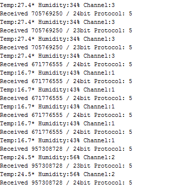
...the output is:

I spent a few hours into this, mostly understanding the rc-switch library and flashing the fake Arduino Nano with a fake PL2303HX serial converter. I've never seen so many blue screens in one day - until now.
As a bonus I've also decoded some RF-controlled outlets bought from Lidl 10 years ago. They were using the Quigg protocol*. Both these decoders will be opensourced once the code is cleaned up a bit.
If I were to do it again I would use the Stellaris Launchpad - it has step-by-step debugging and hands-free flashing.
*Actually, I was able to decode the RF outlets with the rc-switch library and the Stellaris, around one year ago, but somehow I could not do that with the Arduino Nano at the present time.
Hello! I have problem with Decoding wireless weather sensor data.
ReplyDeletePlease give me arduino code and modify rc-switch library. my email: vitasonline26@gmail.com
Thank you!
Hello! I can't complie above soure code. I think maybe some code missed. Please give me modified rc-switch source code.
ReplyDeletemy email: javacong@gmail.com
It's not made to compile, I haven't had time to make it a full library yet as I want to go a different route - integrate it directly with ESP8266 and have the decoding done via Javascript. The code above is for reference only and nothing else was done to it.
ReplyDelete